The VHS Project

Table of Contents
The Situation
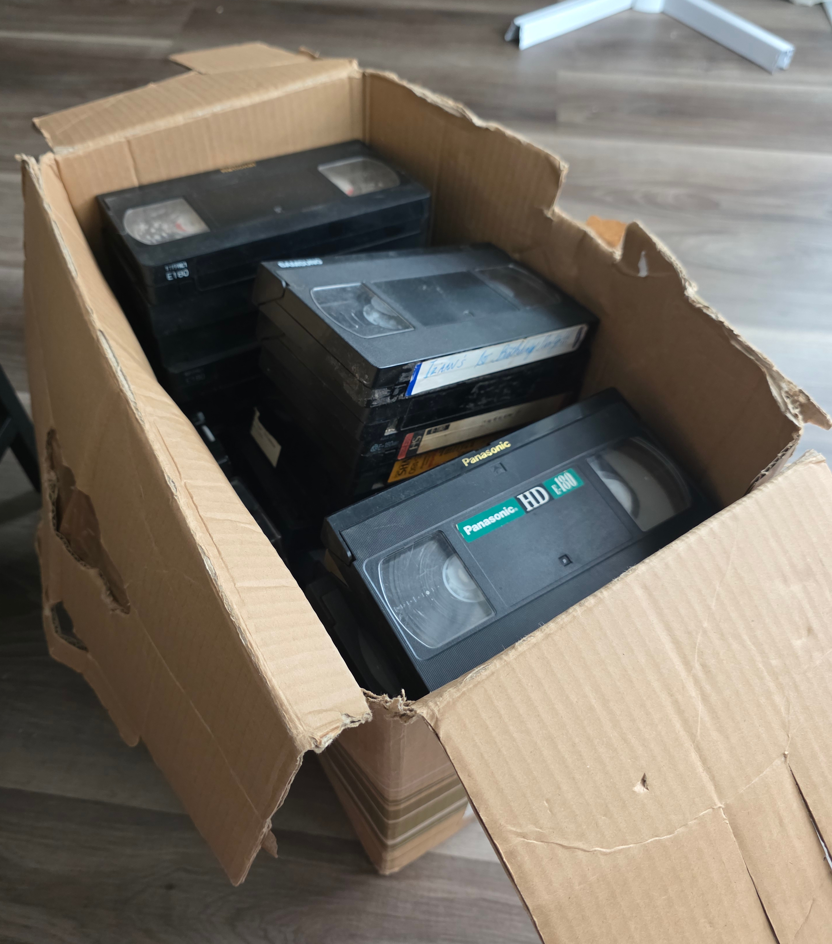
I've come into possession of a box of old VHS and Hi8 tapes containing childhood home videos. They had been filmed around 20 to 35 years ago and were not in the best condition. I think they're coming up on the end of their expected lifespan and are in urgent need for digitisation.
I figured it would be easy enough to buy a cheap PC capture card and do a little digitisation project. But as someone who scores highly on the geek spectrum, I went a little deeper than strictly necessary...
For this article, I'll focus on capture of the VHS tapes. To capture Hi8 I'll need to find a player, most likely a camcorder, which I don't have just yet.
Investigation
I discovered that there are generally two methods commonly used for digitisation, they are:
- Gathering a bunch of hardware like a "time base corrector" (TBC) and a chain of such things like up-scalers, converters and a capture card. Connecting them together and recording the result.
- Opening a VCR, finding where I can tap the raw RF (radio frequency) signal from the tape head, route it through an amplifier, ADC and a capture device straight to my PC, then using software to decode the signal into a video file.
Since my goal was mostly recreational, I just chose the method that looked the most fun and I don't think there's any arguing which option that is.
The Plan
The raw RF capture method is documented on the oyvindln/vhs-decode GitHub wiki, which deserves immense praise for making quite a technical endeavour much more accessible.
After a thorough reading of the wiki, I understood that I broadly needed to accomplish the following:
- Buy the right circuit boards
- Open my VCR, find the RF test points and solder wires to them
- Connect everything together and try to capture a signal
- Process the signal into a nicely encoded video
Before I did any of this though, I went ahead and did a first pass capture using a cheap USB composite video capture dongle. That's simple enough so I won't go over how to do that here. The only thing you need to get right is the capture settings in terms of interlacing, framerate, resolution and such.
I did this so that I'd have a baseline version to compare with after I went through all the trouble of this raw RF capture method. I was also concerned I might ruin some of the tapes in the process and a low quality capture is better than nothing.
A Note About Hi-Fi Audio
I didn't know this going in and it cost me some time. Hi-Fi audio is a specific type of high quality audio recorded separately from the usual baseband audio tracks. You can see how it's laid out on the tape in this diagram:
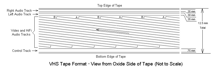
Source: Sam's VCR FAQ
It was a later addition to the VHS format, so not all tapes will have
it. It's also common that home videos won't have this type of audio
signal present. What this means is that the Hi-Fi audio tap point
ENVE/TW4502 only carries a signal for tapes that have it. For tapes
that don't, you'll need to record the baseband audio and join it to the
video, which I will be doing in this post.
Choosing a Capture Workflow
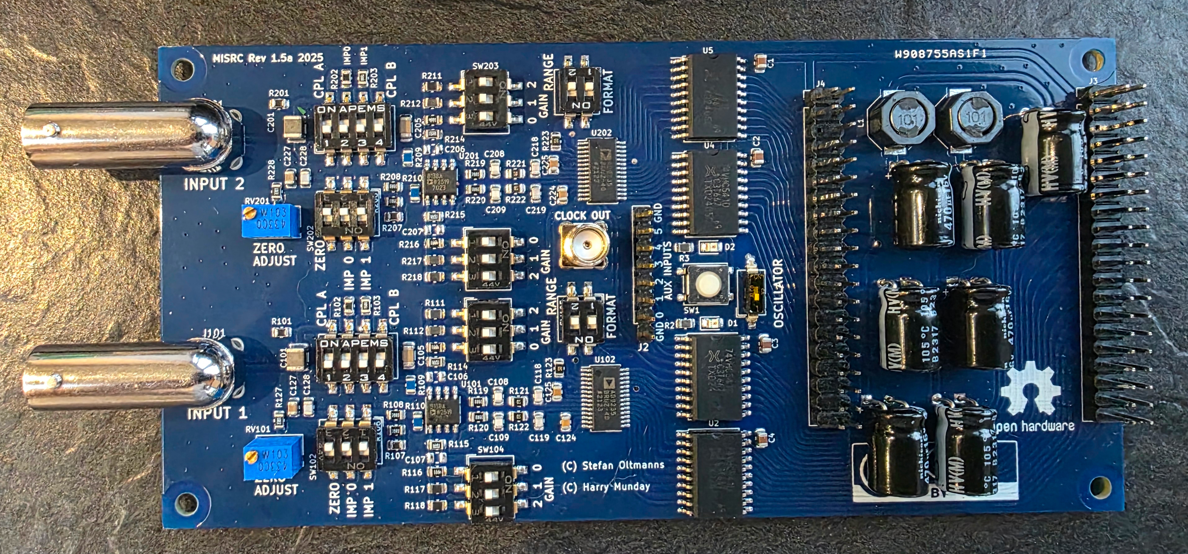
There are many choices to make here regarding which hardware to use. I settled on the MISRC capture device, which is open source hardware that includes much of what would otherwise be separate and rather complicated to put together such as including the appropriate amplifier and clocks as well as supporting both audio and video channels.
So, the setup for using the MISRC requires a few pieces:
- The MISRC board itself.
- A Sipeed Tang Nano 20k FPGA.
- An adaptor to connect the Tang Nano to the MISRC board.
- An MS2130 HDMI-USBC adaptor.
- A PCM1802 breakout board for baseband audio capture
MISRC
To get an MISRC, there are a couple of options. Depending on stock you can order a prefabricated one from this ko-fi shop. Otherwise, you will need to order one fabricated and assembled to order from PCBWay, there's also a guide from the developers on how to make an order.
Sipeed Tang Nano 20K
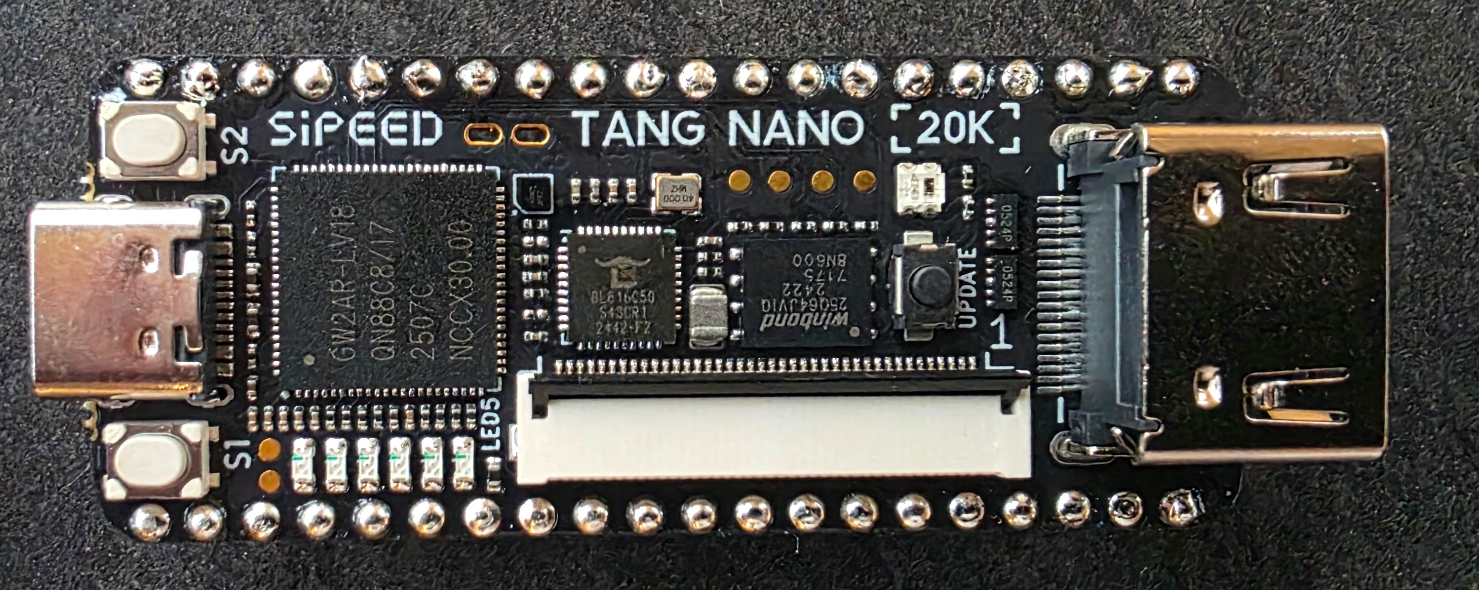
The Sipeed Tang Nano 20k FPGA board is widely available, you can simply order one from Amazon. If available, opting for a pre-soldered one makes sense, as it'll just slot right into the adaptor without any special mounting needed.
MISRC <=> Tang Nano Adaptor Board
Acquiring the adaptor board is similar to the MISRC, either buy one from harrypm's ko-fi shop, or get one made using PCBWay. Going the PCBWay route is a little more complicated however as there's no shared project (at least not that I could find), you need to submit the design files for a custom job. Note that ordering from the ko-fi shop can take a very long time, for me it took over 2 months and this was the last piece to arrive.
MS2130 HDMI-USBC Dongle
The MS2130 HDMI-USBC dongle is a simple purchase available in many
forms on Amazon. The MS2130 name refers
to the specific IC chip which is used in many different capture dongles
of different brands. As far as I know it doesn't matter which brand or
form factor you get. The reason for this specific IC is that it's used
by the HSDAOH project as a cheap
way to transfer a lot of data over USB.
PCM1802 Breakout Board
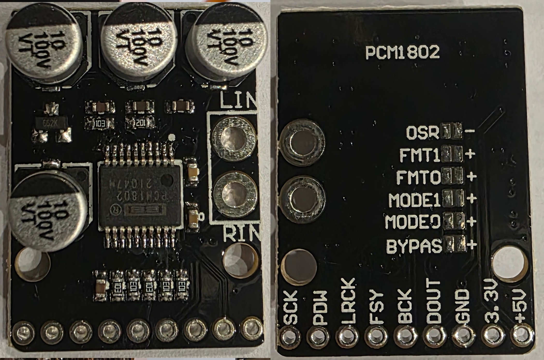
Whether you need to go through the trouble of wiring in an audio ADC like this depends on if you want/need to capture the baseband audio on your tapes. Potentially you're happy with only capturing the HiFi audio which is of higher quality anyway. For me, my tapes didn't have HiFi audio content and the sound was only present as baseband audio, making it essential to capture.
For the version of the MISRC board available to me at the time of writing (v1.5a), in order to capture baseband audio, you need to supply a PCM stream to the AUX pins. Newer versions of the MISRC will support this on-board instead of requiring a separate addon, so check the documentation for the MISRC version you have to decide if you need it.
Setting this up for baseband audio capture is not as straight forward as one would think. The idea is to input the RCA output from the VCR, the clock signal from the MISRC and then capture the PCM output stream via the MISRC AUX pins.
The board has a number of pads on the back you can bridge to configure
various things. For this project, I came to understand we want to
bridge the mode 0 pad, which sets master mode with with an audio
sampling rate of the input clock speed (40 MHz) divided by 512, which
in this case is 78125Hz. That's not a common audio sampling rate, but
not to worry, it's supported by the IC and we can resample it later in
software.
There's a common defect on these boards (more than one actually...)
that was also present in mine. The configuration pads on the back
marked with +aren't connected to Vdd or to anything else. We need to
connect it ourselves in order for the mode 0 bridge to take affect.

Note that +5V is power input while the 3.3V pad is an output. Find
a 5V output on the Tang Nano and connect a wire from there. You can
also see in my picture that I've connected 3.3V and PDW with a
jumper, this is because that's just how you turn the board on according
to the PCM1802
data-sheet.
Connect the BCK, DOUT and LRCK pins to the AUX input pins on the
MISRC, these can connect to any input pin, you just need to know which
is which when you extract the PCM stream later. The SCK pin
represents the system clock input which you need to get from the SMA
connector labelled CLOCK OUT on the MISRC board. You should also
connect GND from this SMA connector since the clock signal is
sensitive and should be properly shielded.
Soldering Wires to my VCR
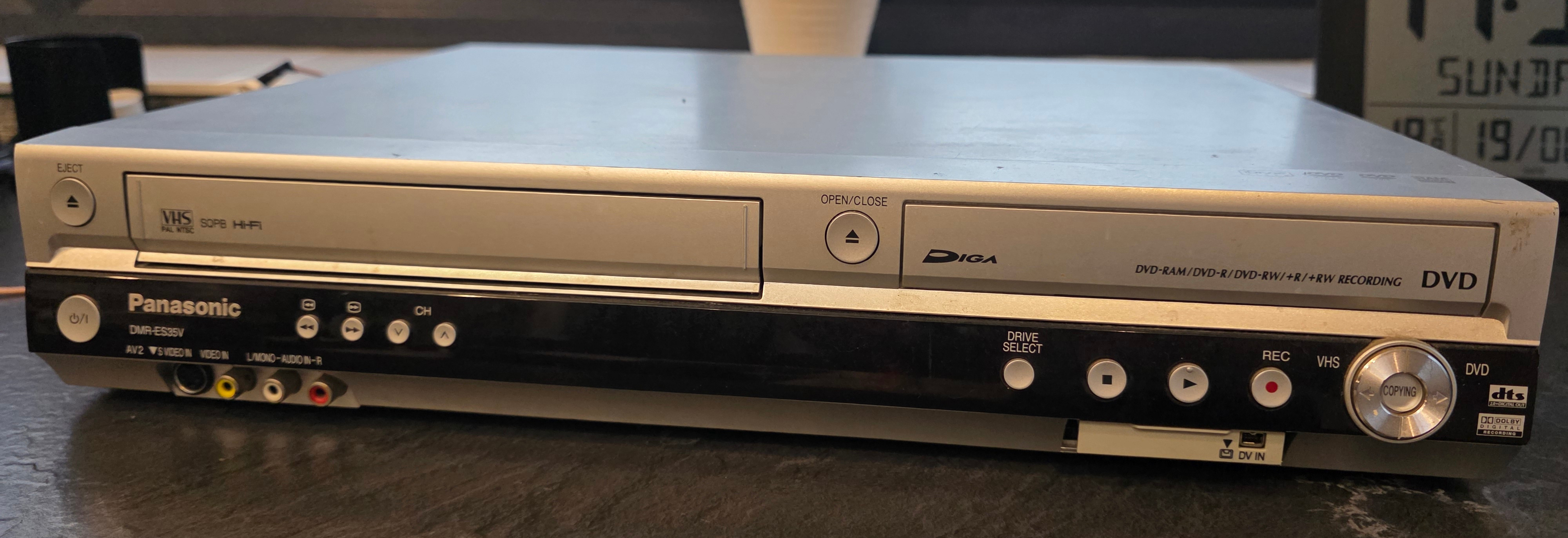
This part required some research. I have a Panasonic DMR-ES35VP, which
is a VHS/DVD combo player & recorder. In order to find the appropriate
test points I needed to tap, I had to scour it's service
manual.
Based on advice from the vhs-decode
wiki
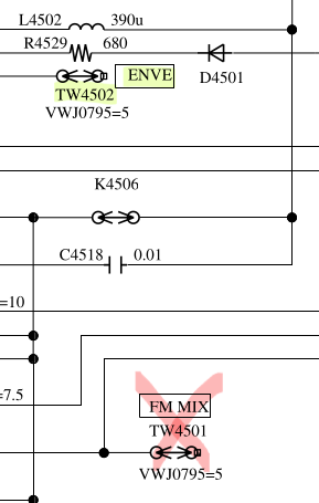
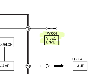
I scanned the pages for something with a label like ENV, VENV or
VIDEO ENVELOPE, as well as AENV, AUDIO ENV, HIFI ENV or FM MIX for the audio.
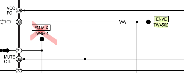
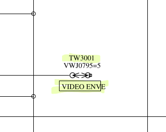
It actually took a long time to find what I thought were the right test
points, but I eventually spotted them to be VIDEO ENV/TW3001 for
video and ENVE/TW4502 for Hi-Fi audio. The labeling varies between
brands, so make sure to read the service manual carefully to ensure you
use the right ones. I actually used the wrong test point for audio when
I first did the soldering, I went with the point labelled FM MIX/TW4501 on the audio circuit, but this isn't what we want, if you
read the manual closely you can see that that test point only carries a
signal during recording. In the case of this VCR, there is a separate
test point labelled ENVE/TW4502 right next to VIDEO ENVE/TW3001,
which is the right one to tap.
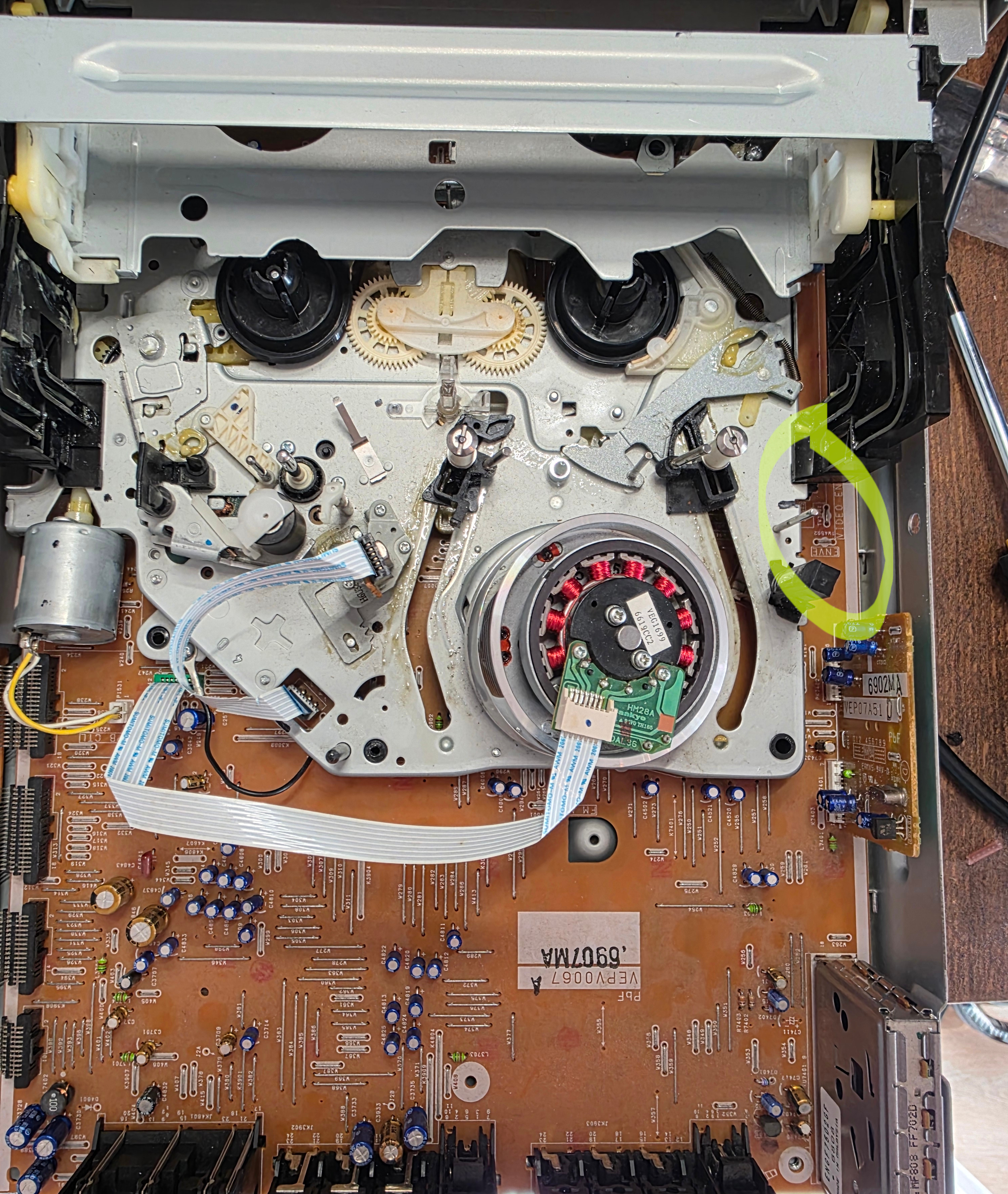
Once the test points were identified, it was time to do the soldering. Since the wires will be carrying very sensitive low power signals, it's important to ensure they are shielded. For this I used coax cabling with the outer sheath attached to ground. To find a ground pin, I used a multimeter in continuity mode to probe various test points in convenient places against the chassis. Turns out there's a very convenient ground wire right next to the test points.

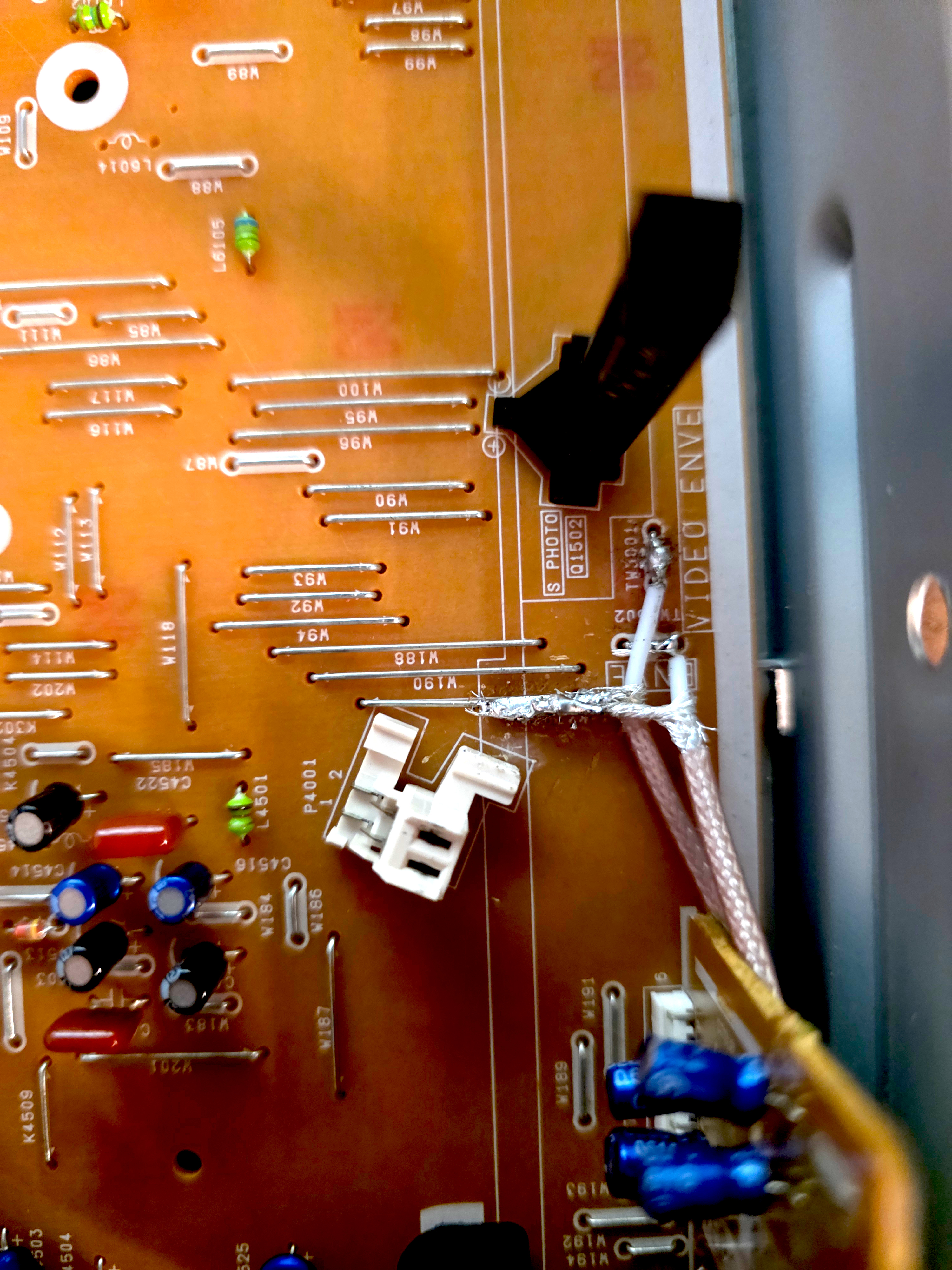
I know my soldering sucks, I don't want to hear about it.
I initially intended to make a hole in the VCR chassis and mount a BNC connector, but the chassis is metal and I don't have the appropriate tools, so I ended up just routing the wires our the side vents and terminating with the BNC connector.
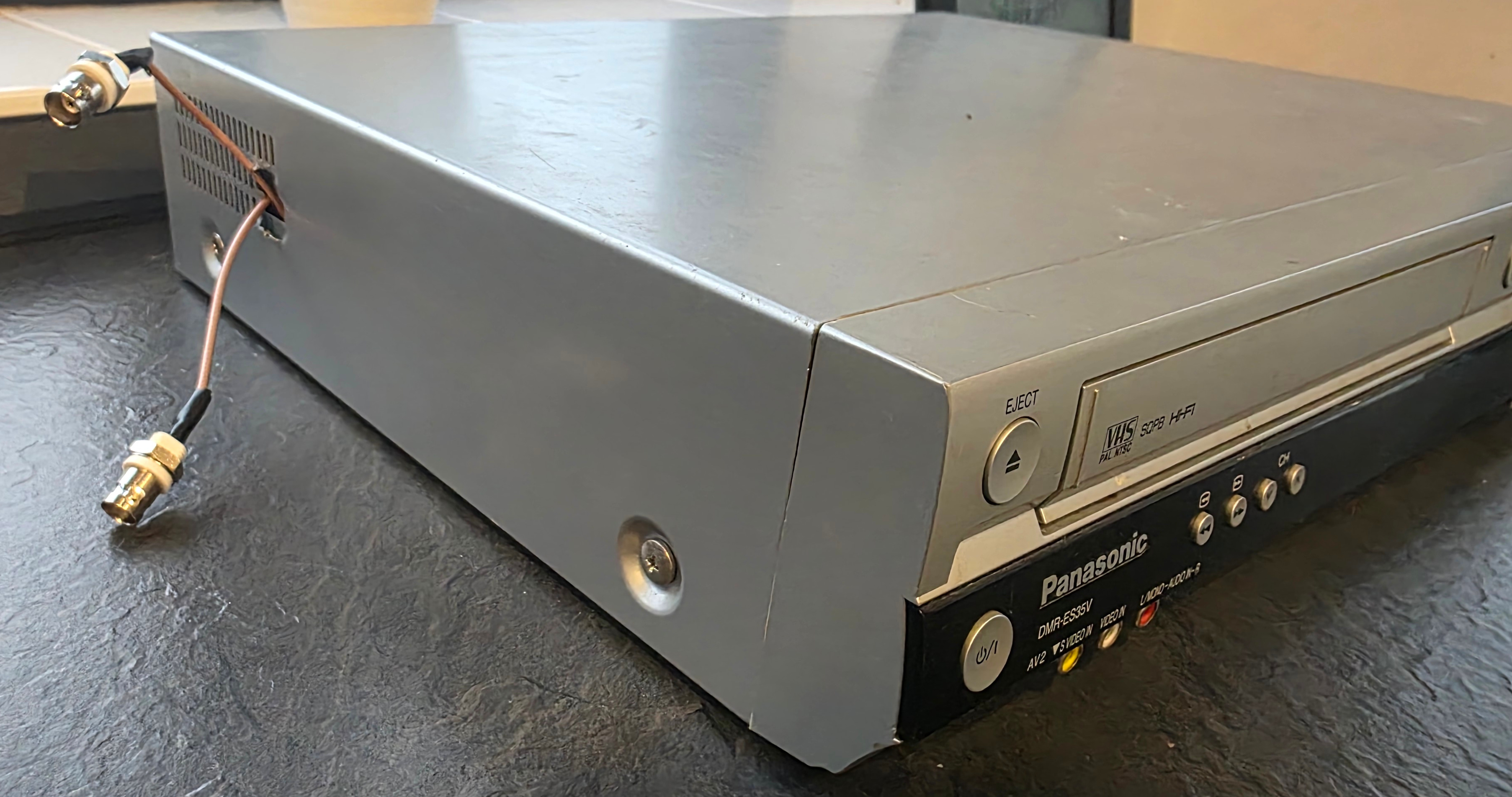
Not going for style...
At this point, the VCR was done and ready to be closed. But while I'm here... I may as well do some cleaning and lubing of the tape mechanism. I added a drop of sewing machine oil into each of the gears I could find and cleaned the cylinder head carefully with some isopropyl alcohol (IPA) and a microfibre cloth. The advice I followed was to slightly wet the cloth with IPA then steadily hold it against the cylinder head while slowly using your finger to rotate the head around a few revolutions (without touching the surface). The main idea is not to swipe the cloth perpendicular to the grooves, which might cause damage or snag and trap lint inside.
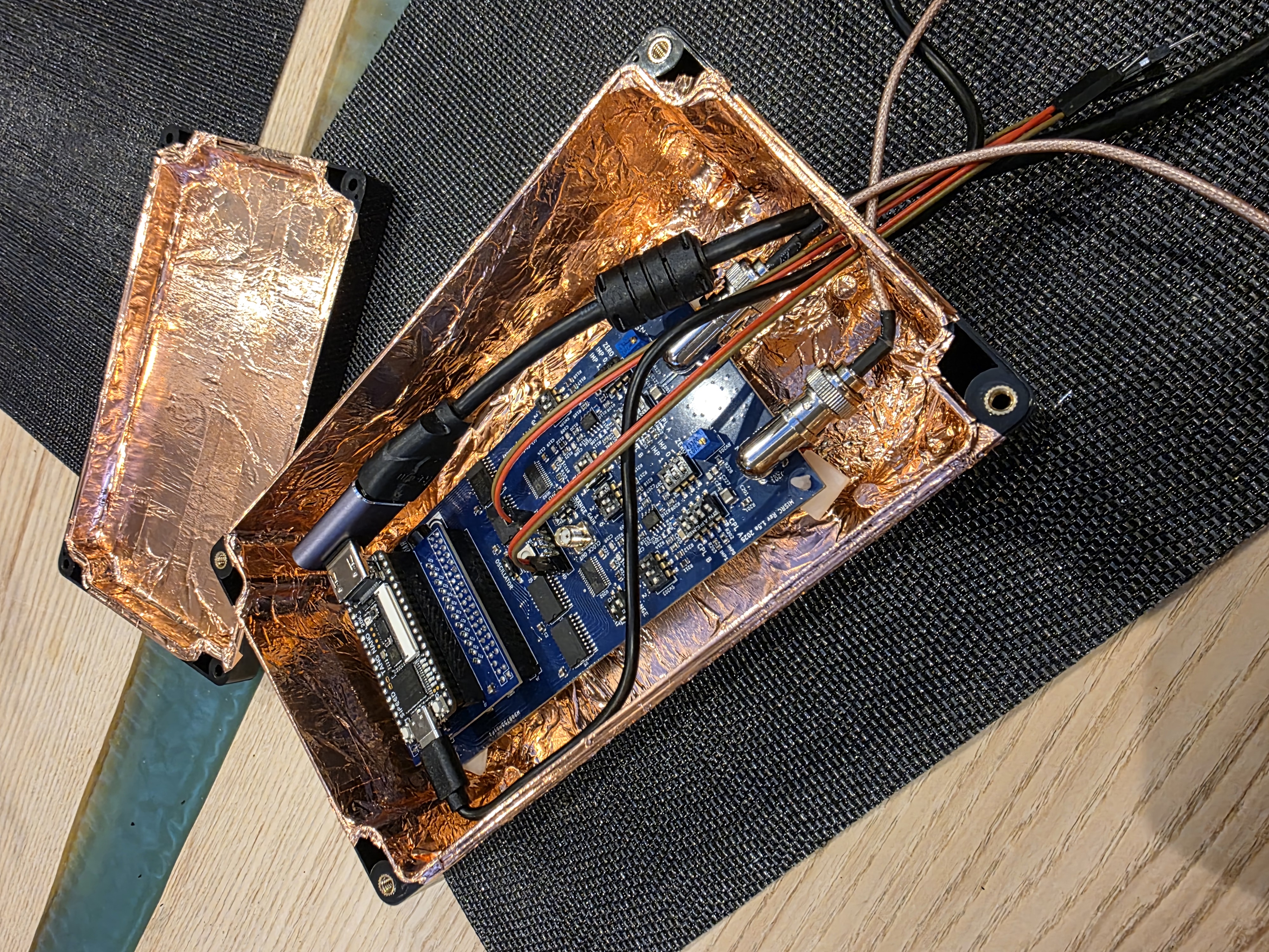
Shielding
To give your signal the best chance, you need to consider end to end shielding for EMI (electro-magnetic interference) protection. I decided to house the components in a plastic project box with the inside lined with copper tape. If you do the same, make sure to cover all the caps and to ensure that there's a continuous electrical connection to every point in the shielding. You'll also want to solder a ground wire from an MISRC ground pin to the chassis shielding (just one).
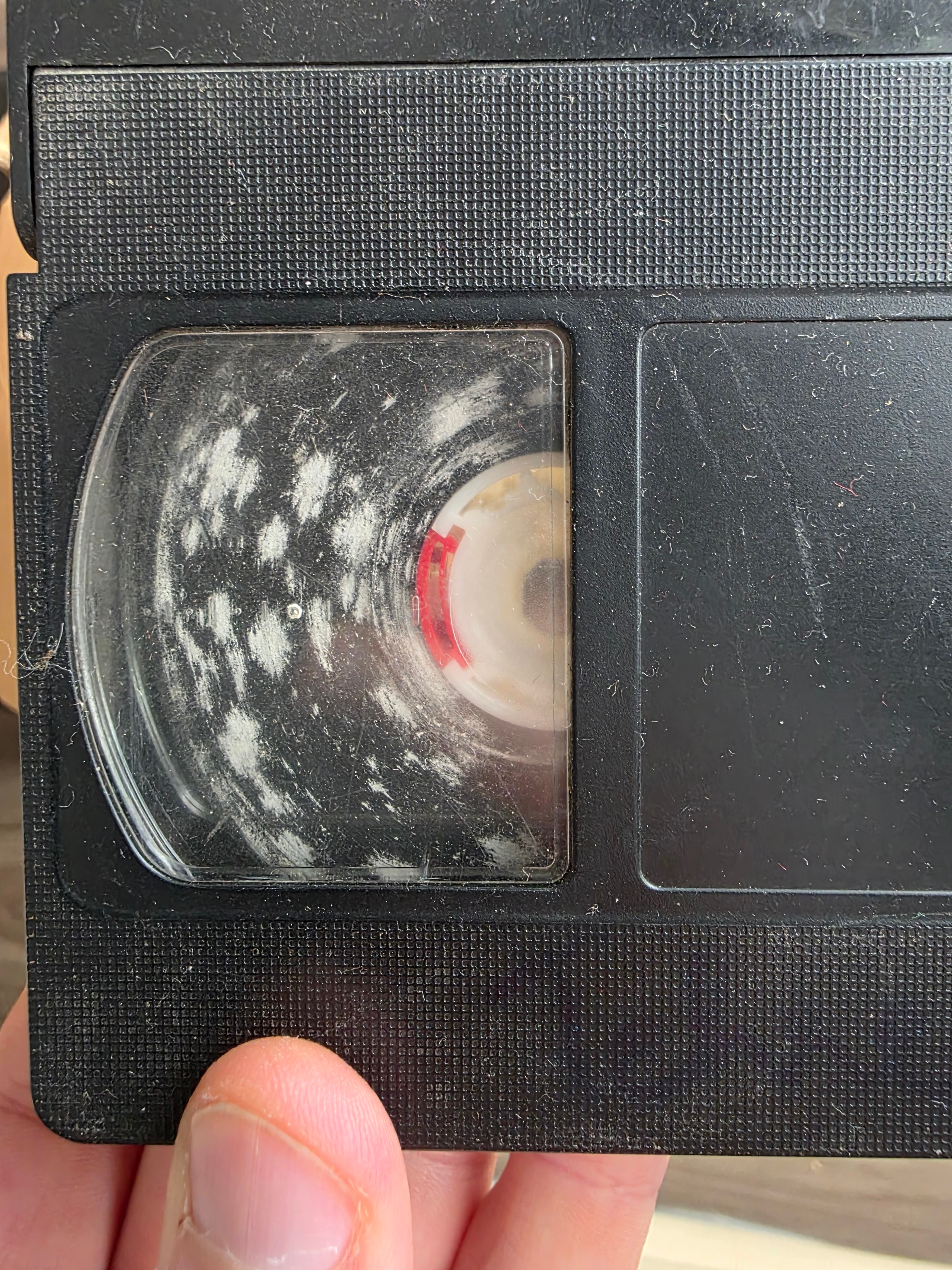
Tape Cleaning
Before capturing from my mouldy tapes, I wanted to clean them. I tried a method where you let it run through the VCR in fast-forward while holding a lightly IPA wet lint-free cloth against the tape. I really didn't like this as it was awkward to hold the cloth properly and my VCR was very sensitive to ambient light with the lid off. It also didn't clean the insides of the cassette where there is bound to be more mould.
So I went looking for an off-the-shelf VHS tape cleaner and found this VHS mould cleaner from VHS is Life. It did a phenomenal job.
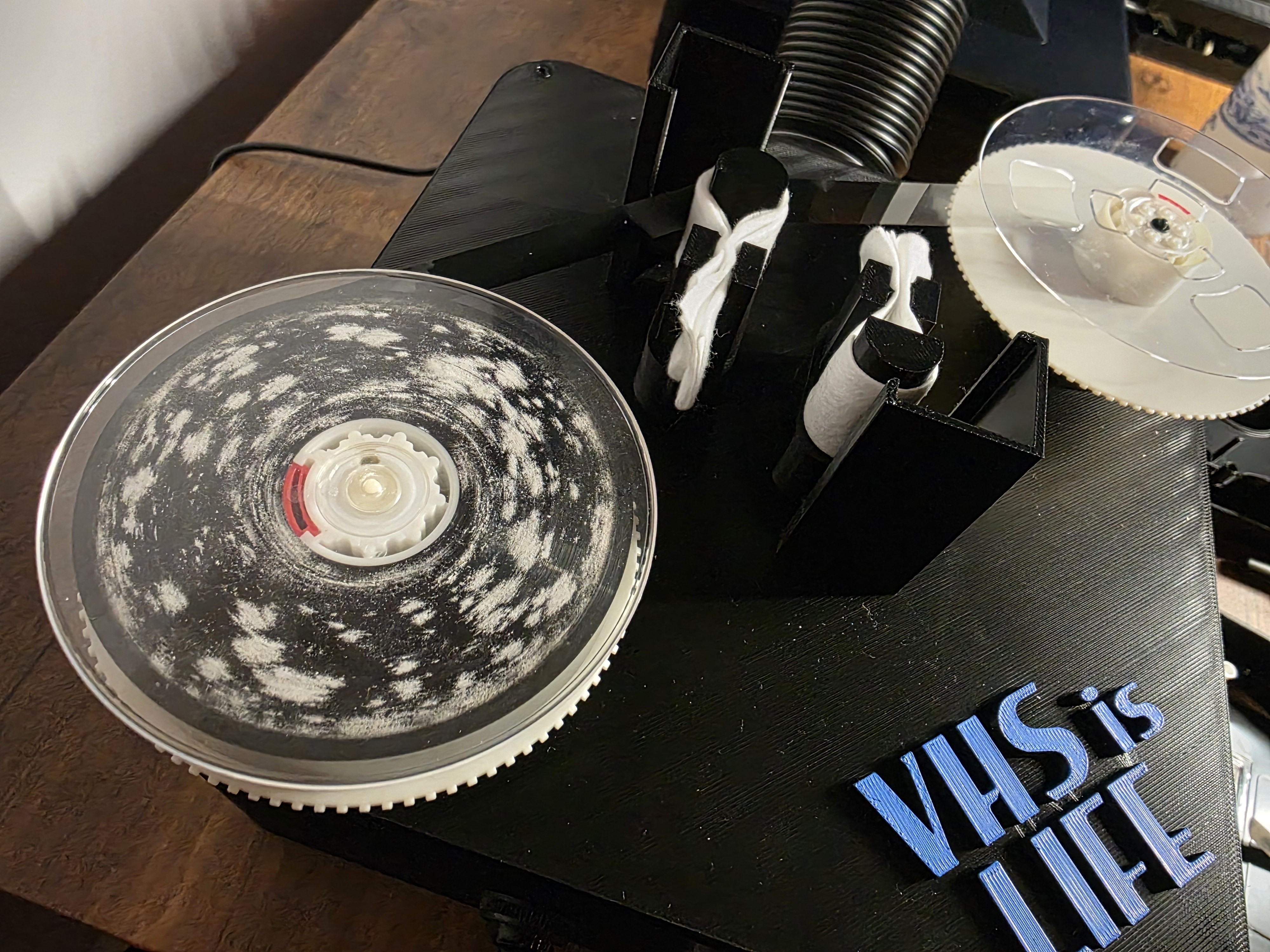

Before and after cleaning.
The cleaner in action.
Capturing a Signal
With all the pieces assembled, I now tried to get it all working. Connecting everything together is straight forward and the software is very easy to use, although a little tricky to install.
To make a capture use the misrc_capture utility:
misrc_capture -p -f -l 8 -a video_rf.flac -b hifi_rf.flac -x baseband_pcm.binWhat you want to see is a clean progress output without any notices about clipped samples being dropped. Samples are clipped when they are too low or too high and it means that something is wrong with the capture.
You have a few settings to tweak on the MISRC via the dip switches. I am not knowledgeable in this domain, but I've figured it out to a degree I'm happy with for myself, so don't fully trust what I have to say.
Think of the RF signal you're trying to capture as a wave-form centred on some voltage. The MISRC can be configured to capture a signal within either 0-1V or 0-2V. You want to ensure the full signal fits inside either of these ranges and that the signal covers as much of the range as possible. This allows the ADC to digitise the interesting parts of the signal using all the resolution it supports.
To centre the signal, you can either enable AC coupling or use DC coupling and adjust the bias pots next to each BNC input. AC coupling effectively removes the DC component and centres the signal automatically in a way I don't fully understand 🤷♂️.
Once you're confident that you have the signal nicely centred in the capture range, increase the amplifier gain incrementally until you see some clipping, then take it back one step. It's not easy to do all this without the right tools like an oscilloscope, but hopefully this conveys the idea.
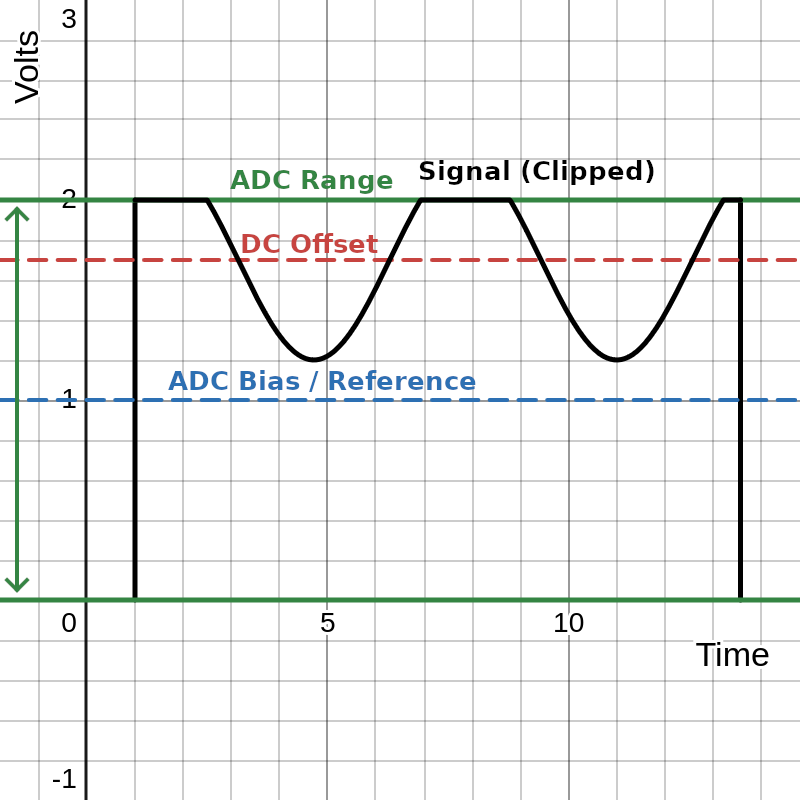
A DC offset with clipping
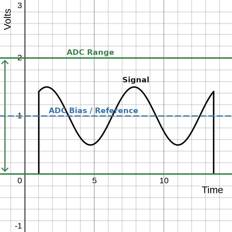
Centred properly

Amplified to use the full range
Captures are very large, expect about 120GB per capture stream (video/hifi/baseband) per hour! You also need a lot of space for processing them into tbc and video files which can be equally as large. I recommend that you have a few TB available and do one tape at a time or risk running out of space and having to start again.
Turning it into a Video
The misrc_capture command will have output three files
video_rf.flac, hifi_rf.flac and baseband_pcm.bin. We can decode
each of these and combine them into a single video file.
Video Component
Take the video_rf.flac files and run it through vhs-decode like so
(set NTSC/PAL as appropriate):
vhs-decode --debug --ire0_adjust --recheck_phase \
  --frequency 40 --pal --threads 8 --tape_format vhs \
  video_rf.flac video_decoded.tbc
This produces a decoded video_decoded.tbc file which we can use to
create the video once we have the audio components decoded. You can
analyze the video_decoded.tbc file with the ld-analyze tool to
inspect each frame. It has lots of useful visualisations to help tune
your pipeline. Of note is the black SNR chart which will tell you
roughly how clean your signal is.
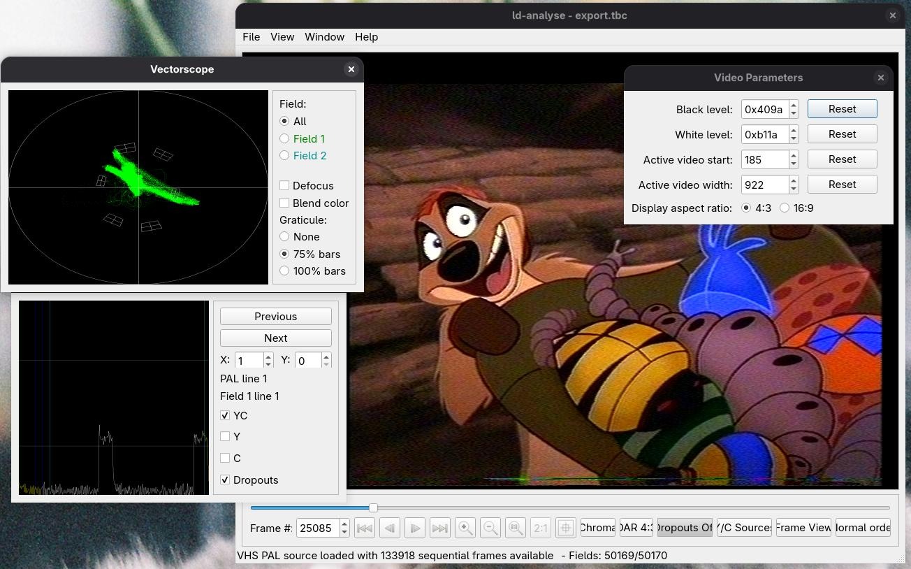
It means no worries.
You can tweak the black/white levels with ld-analyze to improve the
picture, make sure to save the changes you make so that they take
effect when you export the combined video later.
HiFi Audio Component
If you have HiFi audio in your capture, turn it into a flac file with
hifi-decode.
hifi-decode \
  -p -f 40 \
  --normalize --bias_guess --muting off \
  --audio_rate 48000 \
  hifi_rf.flac hifi.flac
Not much to add here, as you can guess, this produces a 48KHz stereo audio file.
Baseband Audio Component
To extract the PCM stream from the AUX input use the pcm_extract tool
on the AUX capture file:
cat baseband_pcm.bin | \
pcm_extract 3 2 5 | \
ffmpeg -y -f s16le -ar 78125 -ac 2 -i - baseband.wav
Depending on how you connected the jumpers between the PCM1802 board
and the MISRC AUX pins, you need to specify the corresponding numbers
(plus 2) to the pcm_extract utility.
pcm_extract <BCK> <DOUT> <LRCK>Muxing it together
At this point you should have video_decoded.tbc, hifi.flac and
baseband.wav. But there's one more thing before we put it all
together.
Aligning Audio
The audio files need to be clock aligned to the video, which you can do with the Auto Audio Align tool.
This tool is written for windows using mono, which can thankfully still
be run on linux. What it does is essentially take the input audio and
align it with reference to the video_decoded.tbc.json file which
contains frame by frame metadata of the video decode.
Baseband
Since the baseband audio was captured with a 78125Hz sample rate, we need to be particular about how it's processed to ensure we don't change the duration of the track.
# WAV → raw s16le stereo
ffmpeg -i baseband.wav \
  -filter 'channelmap=map=FL-FL|FR-FR' \
  -f s16le -ac 2 - |

# Time-align against RF capture (PCM1802 @ 78125 Hz, MISRC @ 40 MHz)
mono VhsDecodeAutoAudioAlign.exe stream-align \
  --sample-size-bytes 4 \
  --stream-sample-rate-hz 78125 \
  --json video_decoded.tbc.json \
  --rf-video-sample-rate-hz 40000000 | \

# Resample → 48 kHz 16 bit FLAC
ffmpeg -f s16le -ar 78125 -ac 2 \
  -af aresample=48000 \
  -sample_fmt s16 -i - \
  baseband_aligned.flac
HiFi
The HiFi audio was decoded into a conventional sampling rate already, but we still need to be sure we give the right values.
# WAV → raw s32le stereo
ffmpeg -i hifi.flac \
  -filter 'channelmap=map=FL-FL|FR-FR' \
  -f s32le -ac 2 - |

# Time-align against RF capture (Hifi @ 48 KHz, MISRC @ 40 MHz)
mono VhsDecodeAutoAudioAlign.exe stream-align \
  --sample-size-bytes 8 \
  --stream-sample-rate-hz 48000 \
  --json video_decoded.tbc.json \
  --rf-video-sample-rate-hz 40000000 | \

# Resample → 48 kHz 16 bit FLAC
ffmpeg -f s32le -ar 48000 -ac 2 \
  -af aresample=48000 \
  -sample_fmt s16 -i - \
  hifi_aligned.flac
Finally
Now you can encode the video and both audio tracks into a conventional
video container with tbc-video-export.
tbc-video-export \
  video_decoded.tbc \
  --audio-track hifi_aligned.flac \
  --audio-track baseband_aligned.flac
This will create a video_decoded.mkv file, a conventional video.
Archive vs Viewing Copies
You've now created an "archive" copy of the tape which is suitable for
long term storage as a master. If you have the space for it, you can
also keep the raw RF files (video_rf.flac, hifi_rf.flac and
baseband.bin). This will let you take advantage of improvements to
the vhs-decode software in the future for better decodes.
You can probably tell that it's not the best for actual viewing since it has a lot of combing from interlacing and it's generally not as clear as it could be. What you can do from here is produce a "viewing" copy, which is what you would typically share with others.
For this I recommend reading this gist by namazso which explains the concepts involved and provides a really nice vapoursynth script which I used for the samples below.
Results
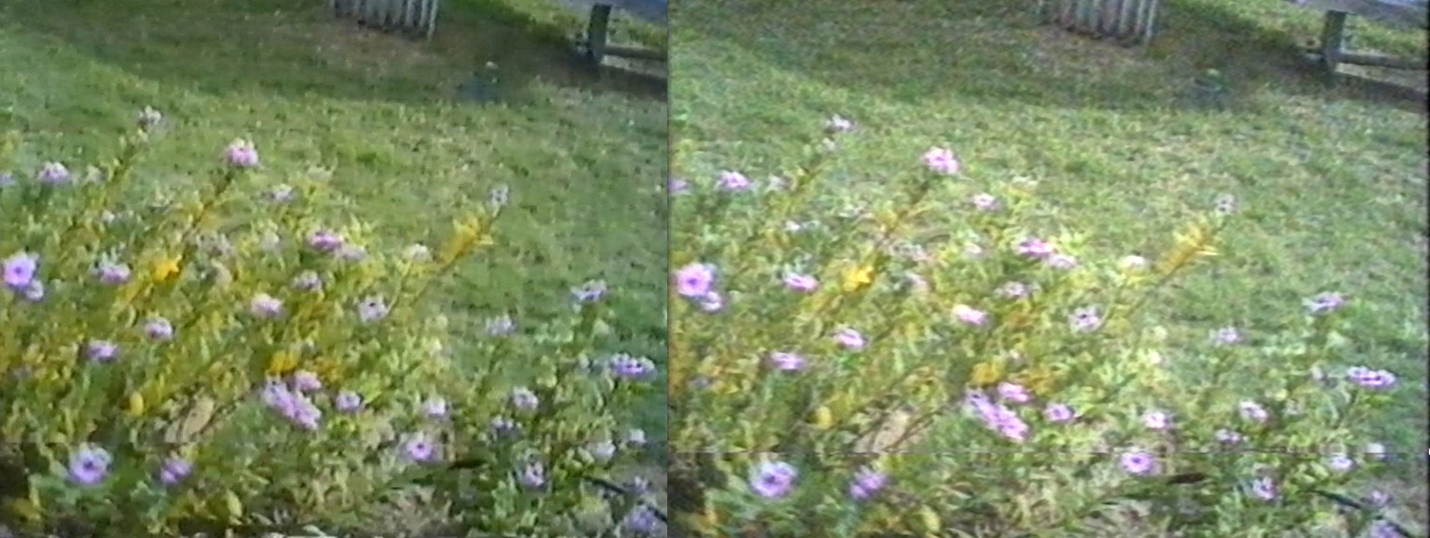
The difference in quality isn't mind blowing, in fact it's rather subtle. The first-pass cheap usb composite capture I did applied strong noise reduction and boosted saturation which washed out some detail detail. I haven't played much with post-processing, I'm sure you could get even better results with some tweaking.
Left picture shows the cheap usb composite capture, right picture is using that hardware tap with vhs-decode:

Slightly better detail, more neutral and honest colours.
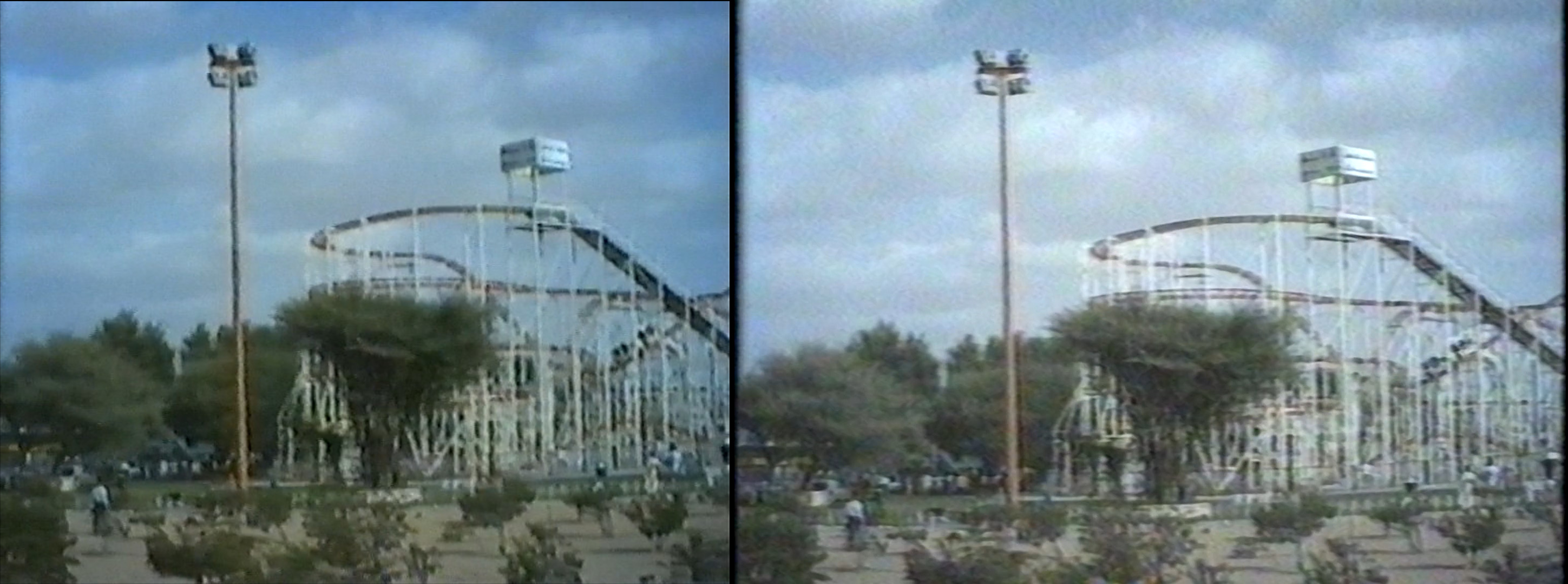
Slightly better detail I guess.

You can now see Mufasa's whiskers and Rafiki's shading.
Honestly the left seems a bit better ¯\(ツ)/¯.
In my opinion the quality gain for tapes this old is minimal. The real advantage is in recovering completely lost sections of tape. There are many cases where the cheap USB composite capture only showed static while vhs-decode managed to recover an image. If your tapes are not particularly degraded, then I'm not sure I could say all this trouble is worth it (unless, like me, you find this kind of thing fun).
Having said that, there's absolutely a lot of room for improvement and maybe with some effort, I could eek out some better quality captures that would make it worth while.
Here's a gallery of extra clips from the tapes I've processed so far:
You wouldn't download a car.
Howdy.
Very interesting.